Frequently Asked Questions
This section is a lie because as of the time of writing, nobody has asked any questions. So this section should probably be named PFAQ (Potential Frequently Asked Questions)
Table of Contents:
- Does this work with PxMatrix?
- Will it work with my display
- What do I do if the Trinity does not fit correctly into my display?
- What pins are used by the display
- What pins are available to use for sensors etc
- Can I connect a SPI sensor/device to the Trinity
- My colours are mixed up/not right
- Does it work with the Pixel Purse?
- Why is it called the “Trinity”?
Does this work with PxMatrix?
No it does not, it is designed to work with the I2S-DMA matrix library
Advantages of the i2s version:
- Simpler to use than PxMatrix
- Does not need the ribbon cable to the out connector
- I2S library is faster - Check out Aaron Christophel’s FPS comparison!
- It has a better chance with working with multiple number displays. PxMatrix supports multiple displays, but struggled to handle over 3. The I2S library has a better chance of working with more (@MLE_Online has tested it with 4 so far)
For future projects I will use the i2s version as my go to.
One advantage of PxMatrix is that it has more support for different styles of panels. Some of the matrix panels have strange layouts and scan patters which PxMatrix can handle.
Will it work with my display?
Honestly, I can’t answer that for sure, all I can say is it should work with any display that works with the ESP32-HUB75-MatrixPanel-I2S-DMA. I can’t guarantee that all display’s will work.
The Trinity has mainly been tested on 64x32 and 64x64 Matrix panels.
Even links to displays I have bought in past that work are subject to new stock/revisions (this happened previously).
What do I do if the Trinity does not fit correctly into my display?
These matrix panels come in a huge variety of shapes and designs and it’s impossible to design something that fits them all, but don’t worry, I have a work around!
Included with each Trinity is a 2x8p stacking header, you can insert this into the input connector of the matrix panel and then plug the Trinity into that, this will raise the trinity up a CM or so. It is surprisingly solid!
What pins are used by the display?
The schematic of the product can be found in the hardware section.
Here is a list of pins that are used by the display:
#define R1_PIN_DEFAULT  25
#define G1_PIN_DEFAULT  26
#define B1_PIN_DEFAULT  27
#define R2_PIN_DEFAULT  14
#define G2_PIN_DEFAULT  12
#define B2_PIN_DEFAULT  13

#define A_PIN_DEFAULT   23
#define B_PIN_DEFAULT   19
#define C_PIN_DEFAULT   5
#define D_PIN_DEFAULT   17
#define E_PIN_DEFAULT   18 // This is the only change from the default pins of the library

#define LAT_PIN_DEFAULT 4
#define OE_PIN_DEFAULT  15

#define CLK_PIN_DEFAULT 16
What pins are available to use for sensors etc
The following pins are broken out
The Add-on area:
- 21 (SDA)
- 22 (SCL)
- 32 (Also used by T9 Touch pad)
- 33 (Also used by T8 Touch pad)
- 2 (Shared with the onboard LED)
- 34 (Input only pin)
LDR
- 35 (Input only, 10K pull-down)
UART
- TX
- RX
All other ESP32 pins are used by the matrix
Can I connect a SPI sensor/device to the Trinity?
It is possible to connect SPI devices but some of the default SPI pins are used by the Matrix. I have successfully used an SPI device using the following pins:
#define NFC_SCLK 33
#define NFC_MISO 32
#define NFC_MOSI 21 //SDA
#define NFC_SS 22 //SCL
You will need to use these pins in your SPI.begin command:
SPIClass spi = SPIClass(HSPI);
spi.begin(NFC_SCLK, NFC_MISO, NFC_MOSI, NFC_SS);
SD.begin(NFC_SS, spi, 80000000);
For more details check out the SDCardTest Example
My colours are mixed up/not right
Well thats not technically a question, but I get you!
Some matrix panels have some of the colour channels swapped around for some reason. The most common one I’ve seen is Blue and Green mixed, which seems to lead to a lot of purple images.
To fix the Green Blue issue you can do the following in your display setup:
mxconfig.gpio.b1 = 26; // 26 is usually g1
mxconfig.gpio.b2 = 12; // 12 is usually g2

mxconfig.gpio.g1 = 27; // 27 is usually b1
mxconfig.gpio.g2 = 13; // 13 is usually b2
Using one of the ESP32 DAC pins / What is the “For Bob” section?
By default the I2S Matrix library uses the two ESP32 DAC pins for connecting to the display. When I was designing the Trinity “Bob” asked would it be possible to free up one of these pins, so I created a solution for this.
This solution replaces pin 25 (one of the DAC pins) with pin 33, which is one of the breakout pins and one of the touch pins. If you make this change, 33 will not be usable for anything other than the display.
Please Note: It is possible to damage your board with these steps if something goes wrong so if you are unsure what you are doing, please do not do it!
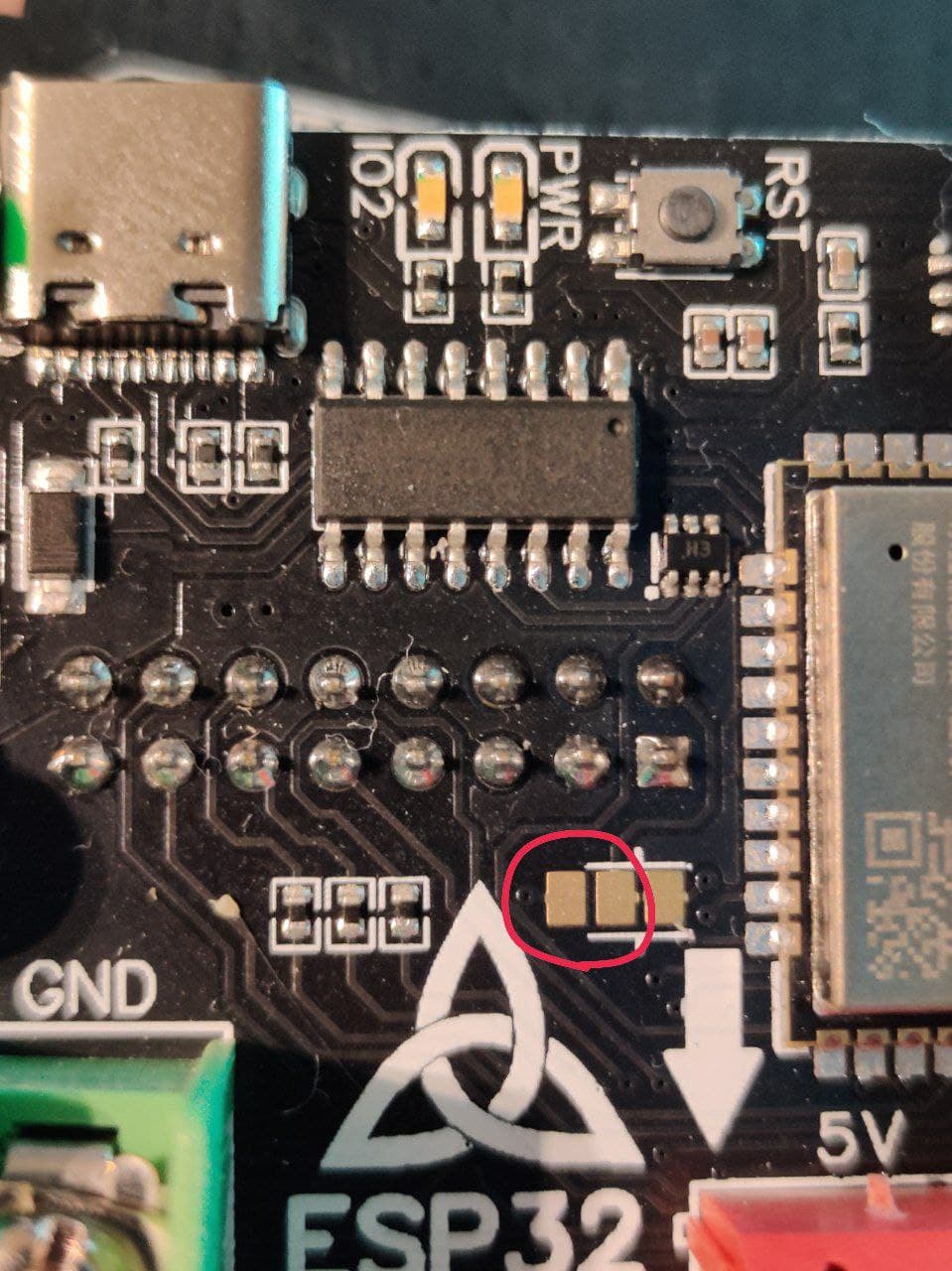
- Locate the 3 solder pads just to top tight of the Trinity symbol
- Cut the trace in-between the right two solder pads highlighted in the image below
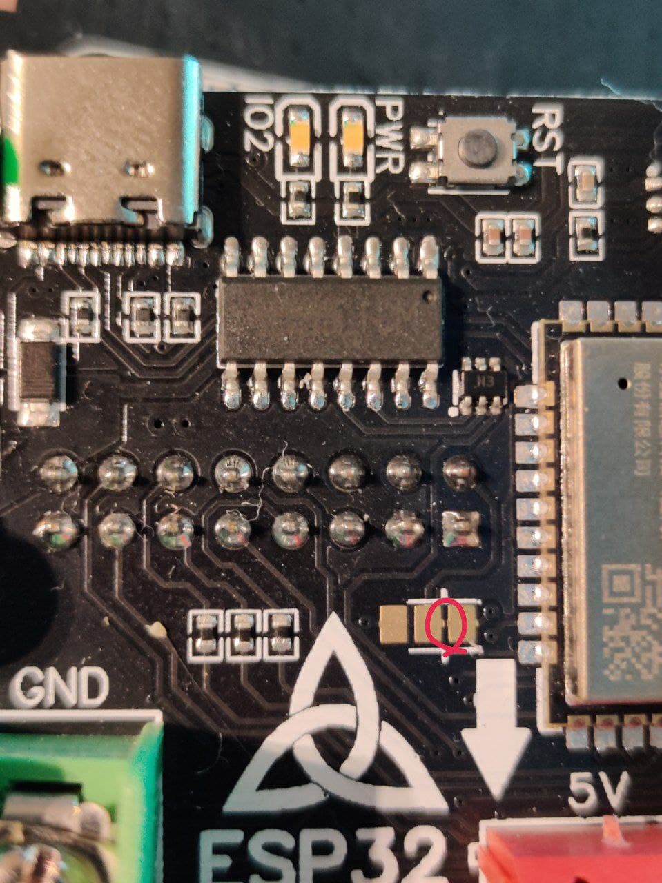
- Solder the left two of the solder pads together
From a hardware point of view that is all you need to do. Pin 25 is broken out just above the ESP32 module (the pins are labeled on the bottom of the board).
In software you will need to add the following to your display set-up:
mxconfig.gpio.r1 = 33;
You are then free to use pin 25 for whatever you need to!
To return the Trinity to the default hardware configuration:
- De-solder the left two solder pads
- Solder the right two solder pads.
Does it work with the Pixel Purse?
I have not tried, but the I2S Matrix library doesn’t seem to support it by default, but there seems to be a trick to get it working and they have provided an example specifically for it here.
Why is it called the “Trinity”?
“Trinity” has a lot of significance for Irish people.
The Trinity Knots symbol is something from Irish/Celtic history and is instantly recognizable as a symbol of Ireland. There are examples of artifacts dating back to the 8th century with Trinity Knots on them.
The Ireland national symbol is the shamrock, one of the main significances of the shamrock is a way to represent the Christian Holy Trinity. It’s said that St Patrick used a shamrock to represent the Holy Trinity when he came to bring Christianity to Ireland.
The most prestigious college in Ireland is Trinity college.
While the above is all true, none of them is why it is called the Trinity. It is called the Trinity after the main female character from the Matrix movies. I felt that “Neo” was too close to “neopixels”